5.3 PROPELLANT EVAPORATION SYSTEMS
This concept is practical only for thermally stable, low normal boiling point propellants, such as cryogenics and near cryogenics, for which it is widely used. It is particularly suitable for cryogenics of low molecular weight, such as hydrogen.
Application in Pump-Fed Systems
Propellant evaporation systems for pump-fed engines usually employ propellants tapped off downstream of the pump and vaporized in a heat exchanger, after which they are used to pressurize the main propellant tank from which they were withdrawn. Figure 5-7 shows a typical heat exchanger design used in an /RP-1 pump-fed engine system. The turbine exhaust gases are used as the heat source. Sometines the vaporized propellant is bled directly from the manifold downstream of the chamber cooling passage if it is the coolant in a regeneratively cooled thrust chamber. As shown schematically in figures and 5-8, the pressurant for the A-2 stage main oxidizer tank is provided by oxygen tapped off downstream of the oxidizer pump and vaporized in a heat exchanger located at the turbine exhaust duct of the oxidizer turbopump. The main fuel tank of this stage is pressurized by bleeding hot hydrogen from the thrust chamber fuel manifold downstream of the thrust chamber cooling tubes. The pressure of both tanks can be regulated by pressure switch/solenoid valve combinations, as shown in figure 5-8, or by regulators. The latter are often preferred, particularly if a narrow band of regulation is essential. In both cases, flow limiting orifices may be used in series, for increased reliability, with valve or regulator design-biased to fail open.
The required propellant flow rate bled for vaporization and main tank pressurization is determined by the main propellant flow rate at the punp inlet (or tank outlet), and by the heat and mass transfer processes within the main propellant tank, which in turn are influenced by pressurant and environmental temperatures. For a given rate of evaporation of the propellant in the tank, average flow rate through the tank vent, and tank ullage gas or vapor condition, the following steady-state correlation can be established:
where
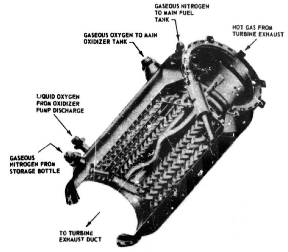 Figure 5-7.-Typical heat exchanger design.
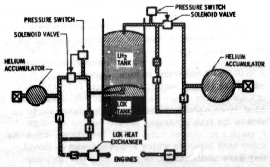 Figure 5-8.-A-2 stage propellant tank pressurization system schematic.
average flow rate through the tank vent, lb/sec main propellant flow rate (per engine) at pump inlet, lb/sec density of the liquid propellant, propellant tank pressure, gas constant of the propellant vapor, lb-deg R temperature of the tank ullage gas, number of engines in the system
Sample Calculation (5-4)
The following data were established for the A-2 stage engine and vehicle systems during steady-state operation conditions:
Main oxidizer flow rate at pump inlet, per engine, (table ) Main oxidizer tank pressure, 45 psia Rate of oxidizer evaporation in the tank, 1.6 lb/sec Average flow rate through the oxidizer tank vent, Temperature of the oxidizer tank ullage gas, Main fuel flow rate per engine, at pump inlet, (table 3-3) Main fuel tank pressure, 38 psia Rate of fuel evaporation in the tank, 4.2 lb/sec Average fuel flow rate through the fuel tank vent, Temperature of the fuel tank ullage gas, Number of engines in the vehicle system, 4 Calculate: (a) The required steady-state flow rate, per engine, bled off for oxidizer tank pressurization.
^4 The required steady-state flow rate, per engine, bled off for fuel tank pressurization.
Solution
(a) The density of liquid oxygen is 71.38 , the gas constant of the gaseous oxygen is .
Substitute this and data given above into equation (5-18) to obtain the required steadystate flow rate of evaporated oxidizer pressurant: (b) The density of the liquid hydrogen is 4.42 , and the gas constant of the gaseous hydrogen is .
Substitute this and data given above into equation (5-18) to obtain the required steadystate flow rate of the evaporated fuel pressurant:
It is noted that some engine specialists prefer to use slightly lower propellant densities; for instance, 71.0 for LOX and 4.4 for . These values consider the fact that storage and vehicle containers, even when vented to atmosphere, have small positive pressures because of vent valve resistance, resulting in slightly increased propellant temperatures. However, since later engine calibration-run evaluations will require corrections for a number of run-to-run engine input deviations, consistent usage of design parameters is probably more important than their absolute value. It is further pointed out that tank pressure regulation through venting, particularly if used throughout the systems duration, is not an efficient method, since onboard gas storage must allow for the maximum vent rate anticipated.
Applications in Pressurized Gas Propellant Feed Systems
The application of propellant evaporation systems to pressurized propellant feed systems is somewhat limited. Evaporation systems can result in lower pressurant storage vessel weight, as compared to stored gas systems, because of higher storage densities and lower storage pressures. However, this can be offset by the higher required pressurant weight per unit volume, particularly for propellants with higher molecular weight. For hydrogen, the principal propellant with low molecular weight, another limitation exists because of the low critical pressure. To obtain reasonable volume increases due to vaporization, the tank pressure must be kept sufficiently below the critical pressure.
It must be further considered that the propellant evaporation concept, when applied to pressure-fed systems, requires a pressurization system within a pressurization system, since a separate stored gas is required to expel the pressurant from the storage vessel as a liquid, after which it is vaporized in a heat exchanger. This system comprises a relatively complicated array of components, line assemblies, heat exchangers, and support structures. It is further complicated because of the auxiliary pressurization system required to initiate the main propulsion system operation. As shown schematically in figure 3-6, the main fuel tank of the A-3 stage propulsion system is pressurized by evaporated hydrogen supplied from a separate liquid hydrogen storage vessel which in turn is pressurized by the stored helium gas. The hydrogen pressurant is vaporized in the heat exchangers, located at the thrust chamber nozzle extensions.
For the various reasons stated, the propellant vaporization principle will be used only for the fuel tank of the A-3 stage, for which it still appears attractive because of the relatively low pressure levels selected, and the low molecular weight of hydrogen. The A-3 oxidizer tank will be pressurized by stored helium gas. This decision was further influenced by the difficulty in handling gaseous fluorine and by its toxicity.